TECHNICAL SPECIFICATIONS
- Outdoor Environment Chamber:
10.5ft. W X 15ft. L X 8ft. T - Indoor Environment Chamber:
7ft. W X 10ft. L X 8ft. T - Outdoor Chamber Temperature Control: 15℉ – 110℉
- Humidity Ratio: 0.005 lbw/lba – 0.013 lbw/lba
- Design Airflow Rate Range: 240-5,000 cfm
- Re-circulate and re-condition water supply tolerance: 1℉ up to 10 GPM
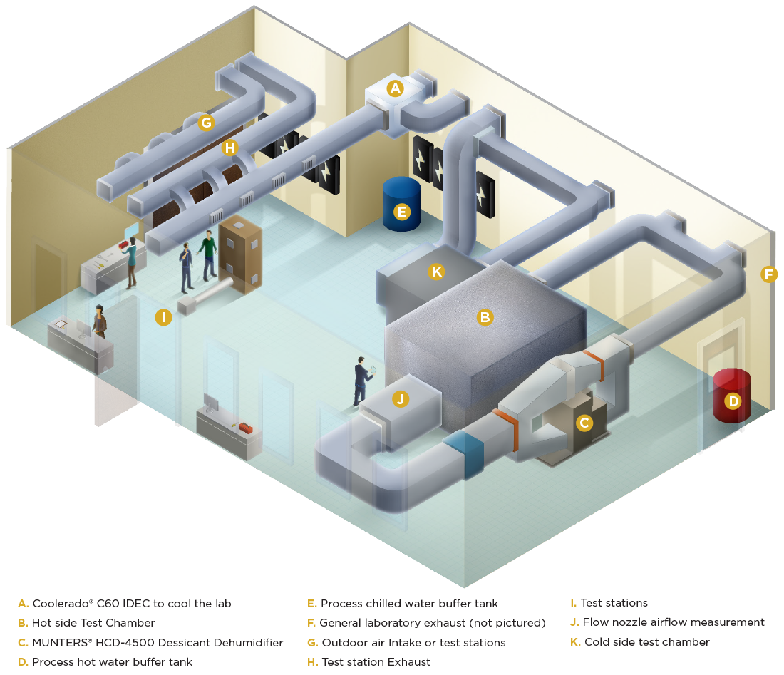
The WCEC built an environmental control chamber specifically designed to test unitary air conditioners in Davis, California. The primary focus of the laboratory consists of controlling two conditioned chambers, one that is 10.5 feet wide, 15 feet long, and 8 feet tall; and a second that is 7 feet wide, 10 feet long, and 8 feet tall. The larger chamber is designed to produce outdoor air conditions and the smaller chamber is designed to produce indoor air conditions.
Temperature and Humidity Control
WCEC's Lab is one of the few labs that can control for temperature and humidity
Using the chamber conditioning equipment, the humidity and temperature of the air in the outdoor chamber can be fully controlled to any temperature between 15°F and 110°F and any humidity ratio between 0.005 and 0.013 lbw/lba. The equipment under test can further increase or decrease the temperature of the chamber if desired. For example, when testing a heat pump in cooling mode, the outdoor air temperature can exceed 110°F as the test unit is a heat source for the outdoor loop. When testing a heat pump in heating mode, the outdoor air temperature can be lower than 60°F because the heat pump is a heat sink for the outdoor loop. The limitation on the temperature minimum and maximum is a function of the test equipment as well as the leakage and heat transfer through the ductwork. The design airflow rate for the outdoor chamber is 240-5,000 cfm, although flow rates up to 8,000 cfm are possible with reduced thermal conditioning capabilities.
Temperature and humidity control of the outdoor air chamber is accomplished by two parallel conditioning paths, through which the distribution of airflow is controlled by two computer controlled dampers. One path contains a heating coil supplied by hot water and an evaporative media humidifier, the other path contains a chilled water coil and a gas-fired desiccant dehumidifier. The hot and chilled water coils have computer-controlled valves to modulate water flow while the humidifier and dehumidifier have on/off control. Modulating the dampers and valve positions allows for precise control of the chamber humidity. The final temperature of the air is then controlled by additional hot and chilled water coils prior to the chamber inlet.
Indoor Chamber
Determining the end result of performance
The indoor air chamber capabilities are designed to provide heating and humidification when testing cooling systems and limited cooling/dehumidification capabilities for testing heat pump systems. Modulating dampers and valves allow for precise control of chamber temperature and humidity. The design airflow rate for the indoor chamber is 240-2,500 cfm.
Sensors utilized in environment chambers
Accurate results
In both chambers, the inlet and outlet temperature and dew point of the chambers are measured with resistance temperature devices (RTDs) and chilled mirror hygrometers. Damper actuators and valves are manufactured by Belimo and are fully controllable over a 2-10V range. Data acquisition inputs, PID algorithms, and control outputs are accomplished with National Instruments CompactDAQ hardware and custom LabVIEW software.
WCEC also has the ability to re-circulate and re-condition (with heating or cooling) a water supply to a specified temperature set point within a tolerance of 1°F at a rate of up to 10 GPM.
CONTACT THE LAB MANAGER
David Braden
dpbraden@ucdavis.edu